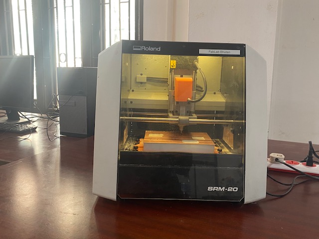
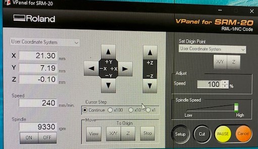
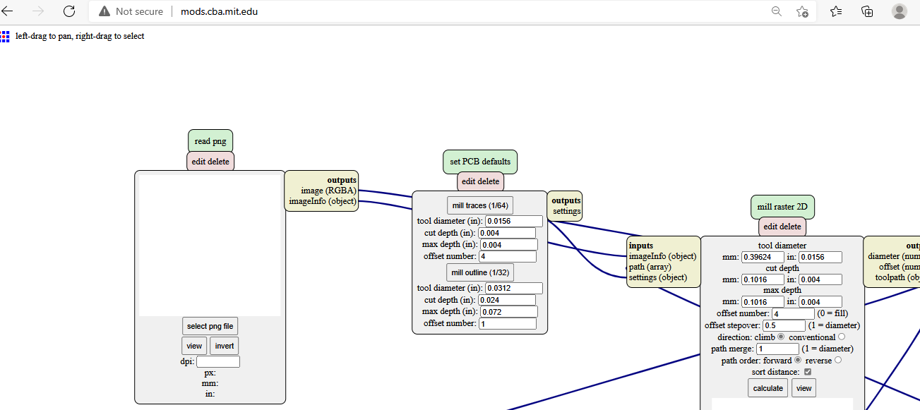
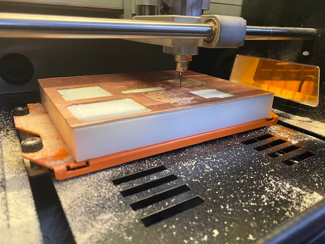
The above given machine is the Roland SRM-20 PCB milling machine that is available in the Fab Mandala, Bhutan and the image of the software in the right is the 'V-panel' for SRM-20 which is used to input the rml file for production through the SRM-20 machine. To convert the PNG image of the PCB board we have to go to http://mods.cba.mit.edu/ as shown in the image below and the following png images are my Echo Hello World board's image and the border png image. When you export it from the Eagle software, you have to be careful to use 1000p for quality of the image so as to avoid improper PCB layout and traces cutting.
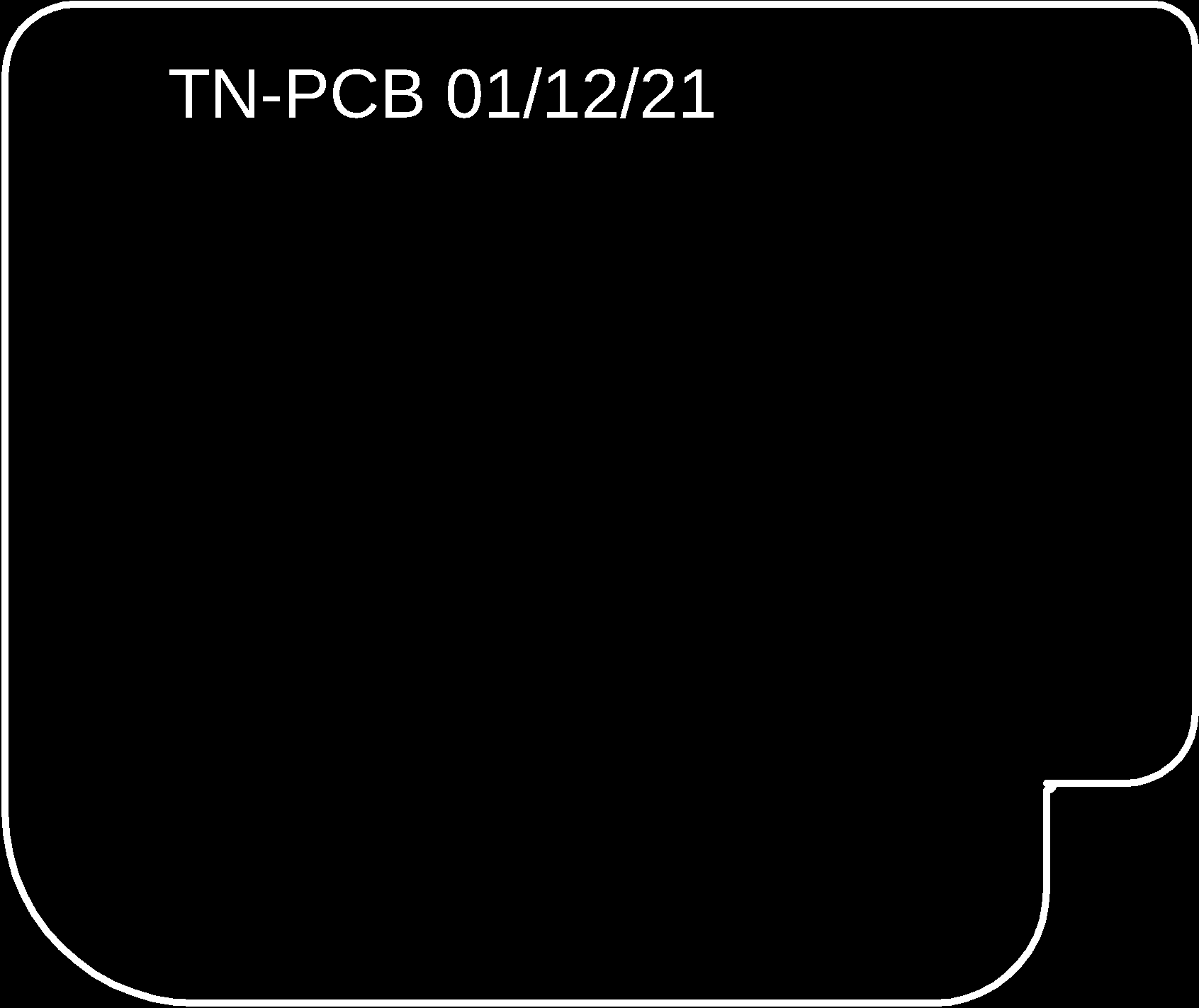
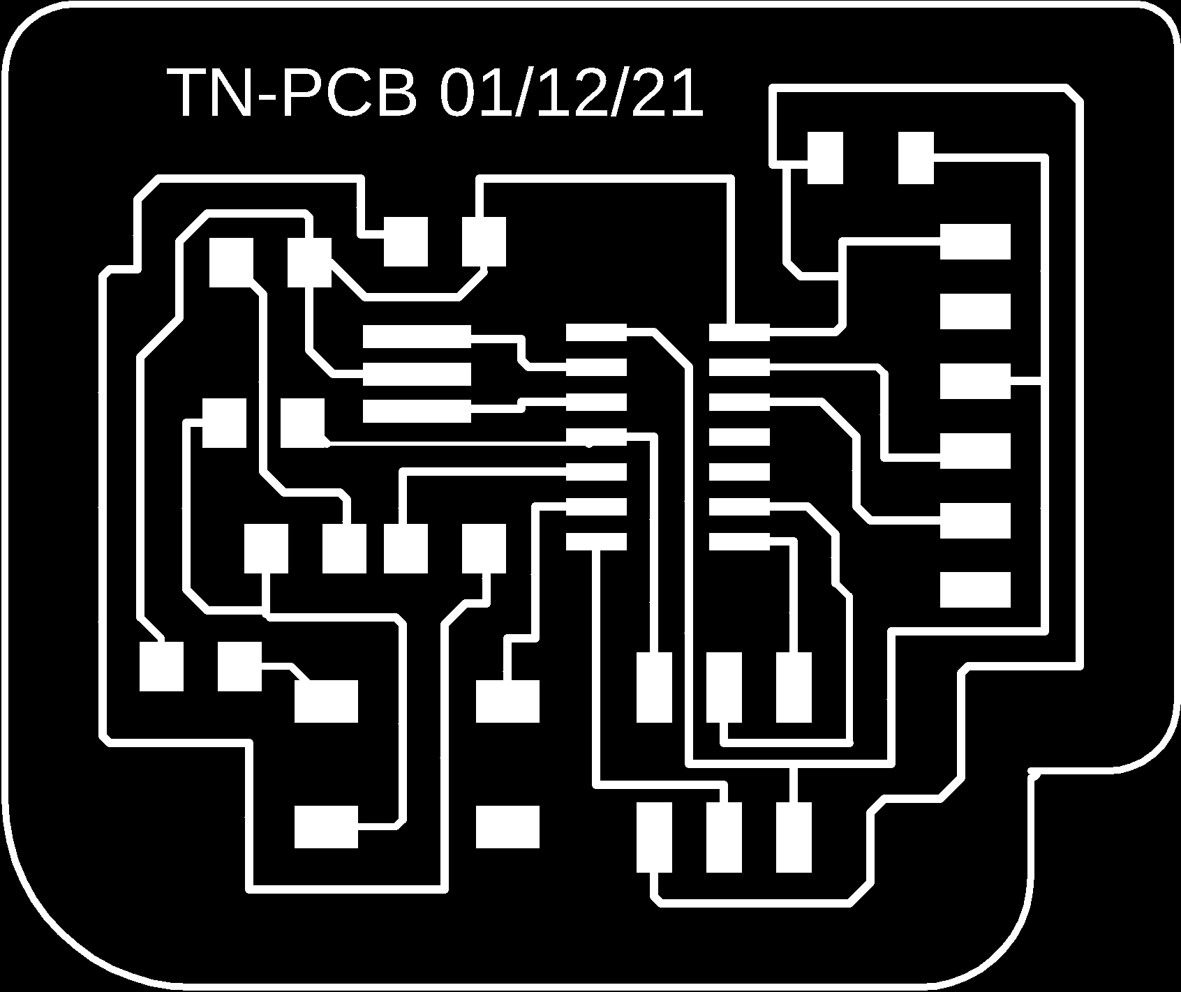
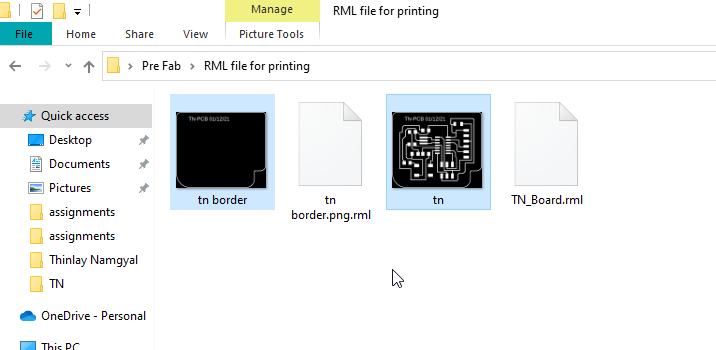
My rml(redline markup language) file of the PCB board and the border was saved with the png files for milling it in the SRM-20 machine. The following image shows my final rml files;
For cutting the border of the PCB we use 0.8 mm(1/32) PCB cutting bit and we have to select it from Mods. For cutting the tracess of the PCB we use 0.4 mm(1/64) trace cutting bit. The code that the SRM-20 machine understands is the G-code. After extracting the rml file, we have to upload the rml file to V-panel for SRM software. Next er have to define the 'x' and 'y' co-ordinates and after doing so we have to do zeroing of the drill bit and to do that we have to release the drill bit to the PCB board and then tighten it as the drill bit touches the copper plate. Now 'z' coordinate is also defined, we have to give command to cut in the software and the SRM-20 machine will start cutting the traces.
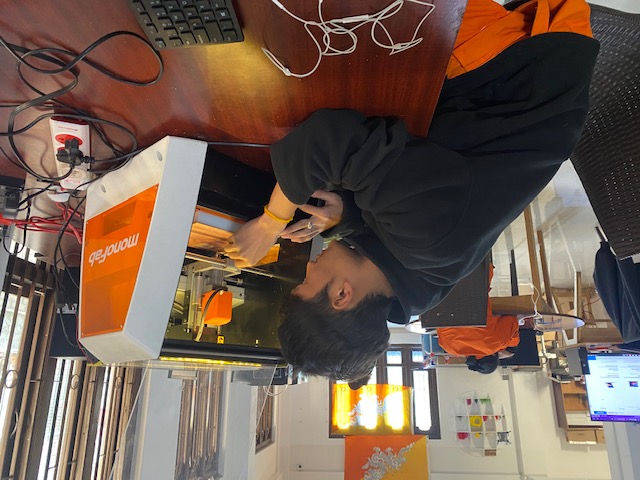
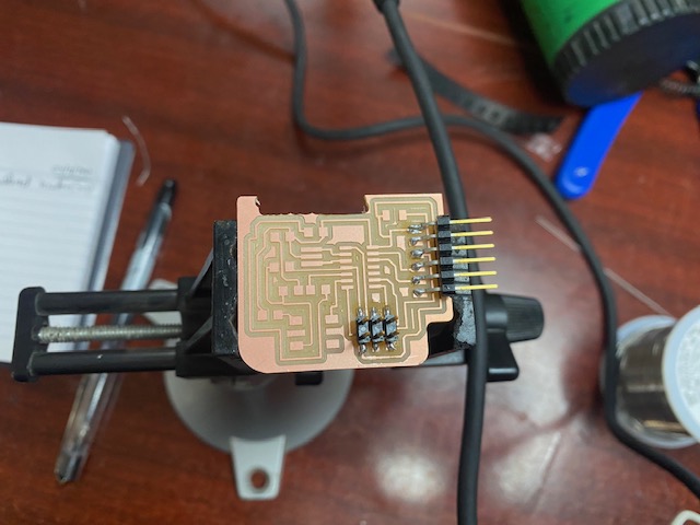
The above image shows me doing the zeroing, now zeroying is a process where the drill bit is positioned just to touch the coppper plate firmly.
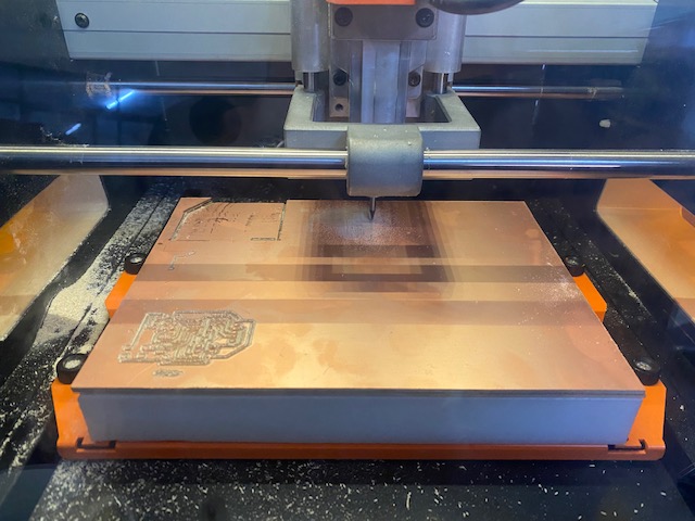
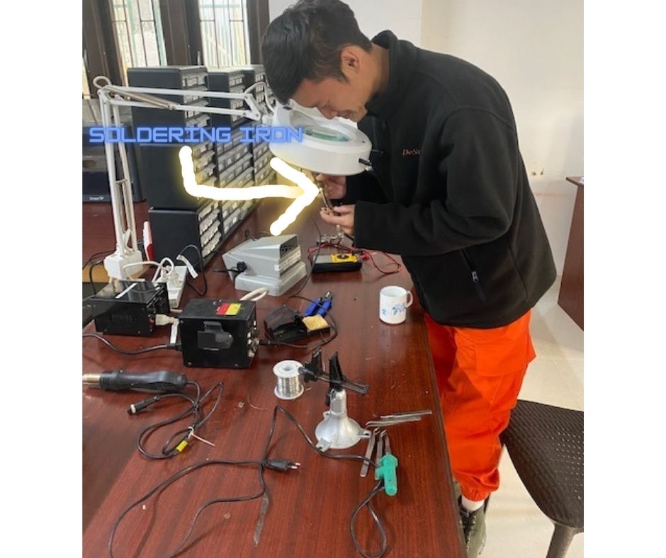
After 15 to 20 minutes, your PCB will be ready for soldering. You have to use a scraper to take out your PCB and clean the machine using a vacuum cleaner. Once you get your PCB, the next thing is soldering. Soldering is a process of joining two or more electronic components together by melting solder around the connection. Since FabAcademy mandates the use of SMD(surface-mounted device) we have to solder all the compones on the top of the circuit board. Now for soldering we use a soldering iron that is heated up in order to melt the solder.
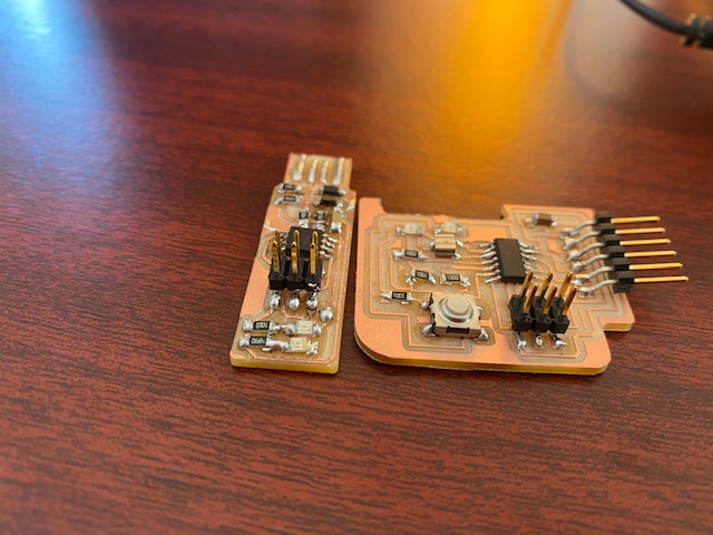
I first soldered the FTDI(Future Technology Device International) header and the 2*3 header pin. After soldering all the components, my Echo Hello World board came out to be something like the following image;
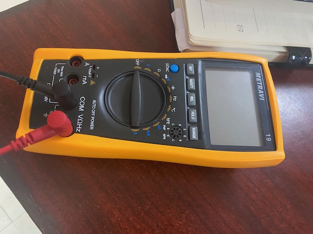
After soldering you have to check whether the connections are perfect and the paths are all connected by using a multimeter. A multimeter measures electrical properties such as AC or DC voltage, current, and resistance. For now we are checking whether the connections are perfect or if we need to solder it again. The multimeter that I used to check the current paths is given below.
Now the programming will be explained in the embedded programming page.