You can download Autodesk Eagle software from here.
Autodesk Eagle is a design software for designing the PCB(printed circuit board). During the electronics design class we were introduced to most of the electronic component and their funcions. The first set of electronic components that we used for our first PCB design are listed below. The components used for designing my first Hello World board are as follows;
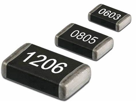
Resisors are passive two-terminal electrical component that implements electrical resistance as a circuit element. It is used to reduce current flow, adjust signal levels, to divide voltage and terminate transmission lines.
Resistance= Voltage/Current (V=V/I)
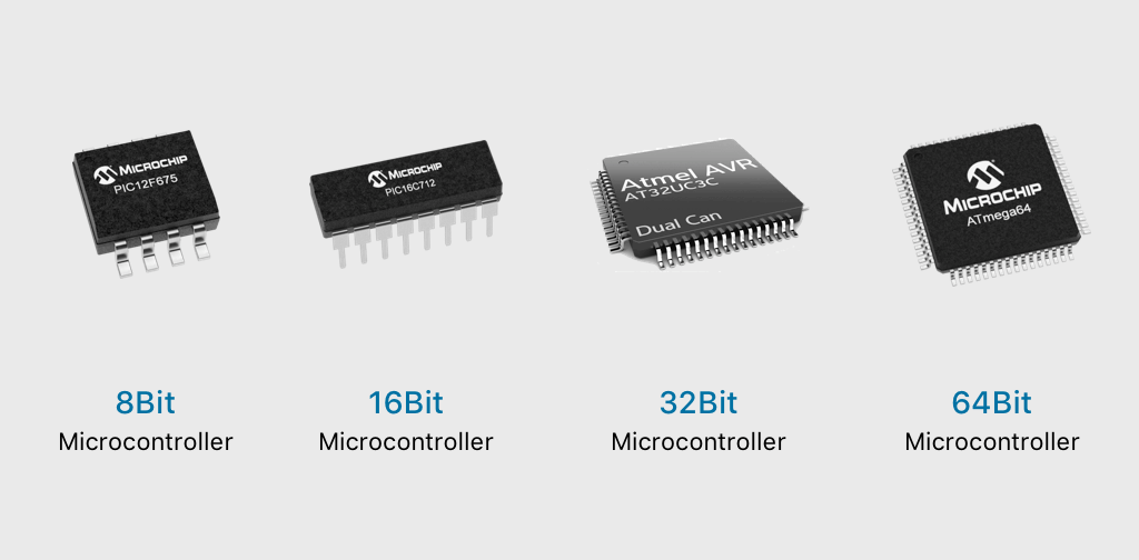
A microcontroller is a small and low-cost microcomputer, which is designed to perform the specific tasks of embedded systems like displaying microwave’s information, receiving remote signals, etc. The general microcontroller consists of the processor, the memory (RAM, ROM, EPROM), Serial ports, peripherals (timers, counters), etc(source-google). You can read more about micro controllers here. text
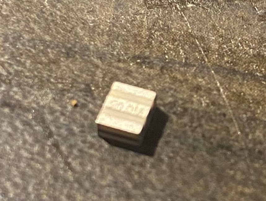
Is an electronic component that can generate a resonant frequency. Resonators cancel out a certain range of sound frequencies. Resonators are used to match frequencies.
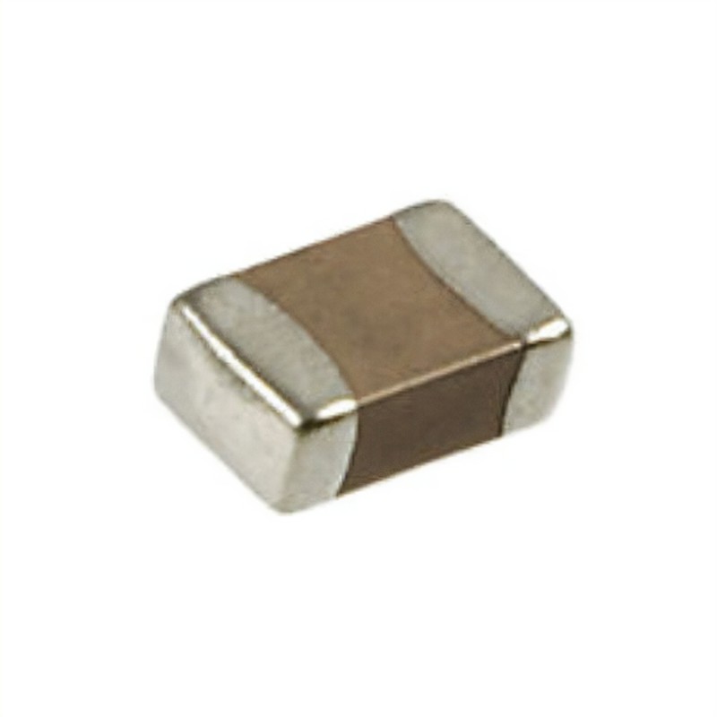
Device that stores electrical energy in an electric field. It is a passive electronic component with two terminals. The effects of a capacitor is known as,'capacitance'.
Unit= Farad.
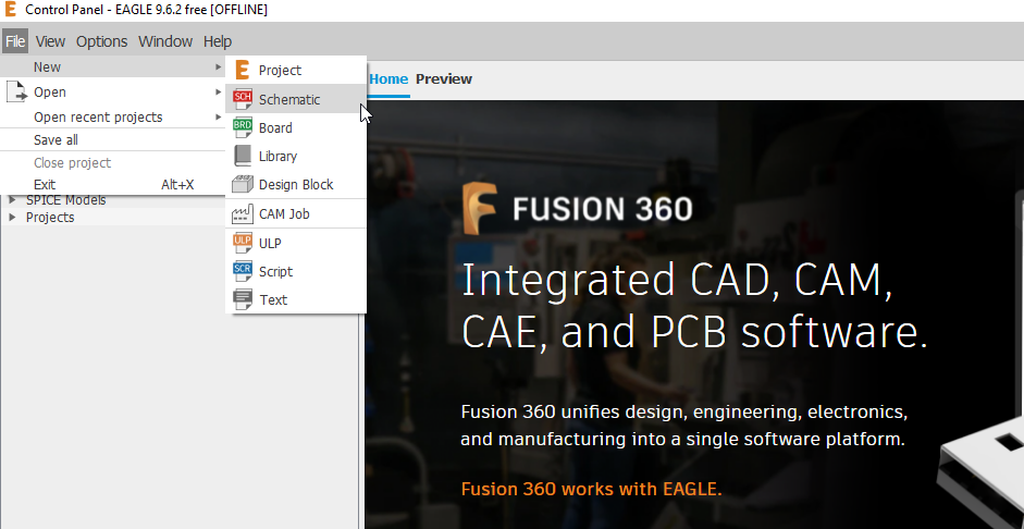
After downloading the software, if you open it then you will find the Eagle software's home window from which we have to go to File>> New>> Schematic just like given in the image below. For the PCB design, we have to first design it and net it in schematic format before doing it in the board mode.
For Fab Academy, you have to first download fab libraries for components to be used in the Autodesk eagle software. you can download the libraries from fab libraries. Once you click on the link you will get the following window
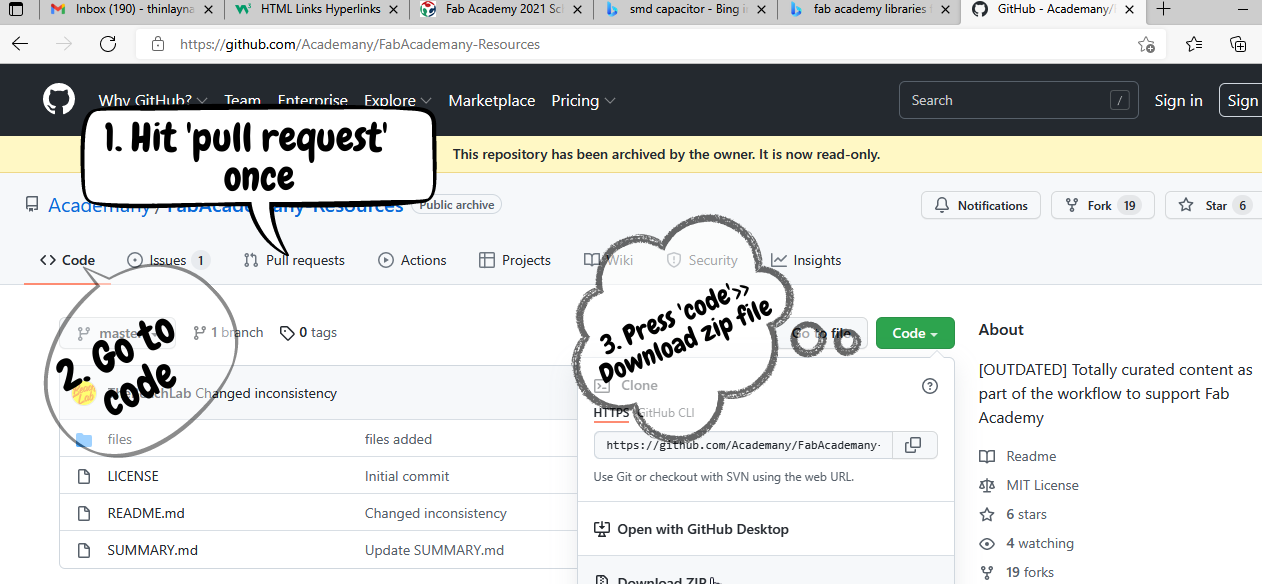
After downloading the zip file, you have to extract the files and through eagle in the schematic view you have to punch the 'use' command and upload the fab libraries and then accordingly use the components.
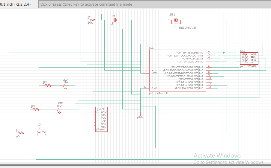
After having added the fab libraries you can start using the 'add' command in the command section and then add the components that you need for your PCB design. The schematic design of my Hello World board is given in the image below.
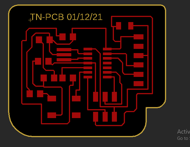
Once you are done with the schematic design, you have to switch to board view so that you can arrange the components in the best way to make the routing successful without any overlaps. The following image shows my Hello World Board's complete routing with size of mill traces also defined.
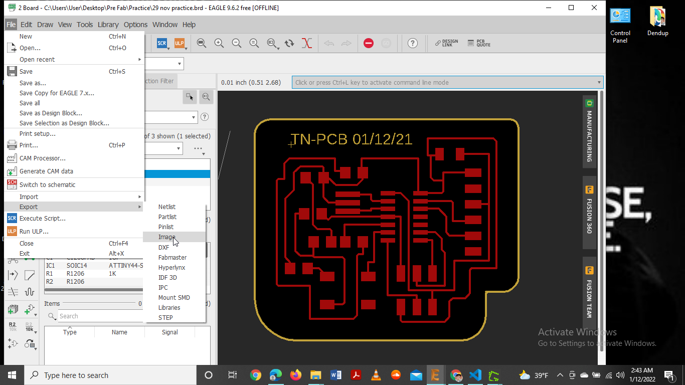
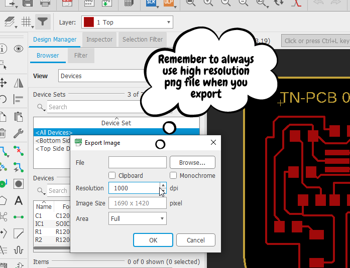
After exporting the png file you have to use mods to convert that png file to rml file which can then be processed using the SRM-20 for your PCB milling.